
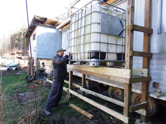
Water tower strength for an IBC tank
I suspect this is a
simple math problem for an engineer, but I don't know where to begin to
determine whether our water tower is going to collapse under the weight
of approximately 2,294 pounds of water. Roland, do you have some handy
load-bearing tables at your beck and call?
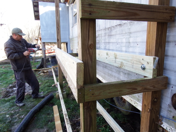
I figure each
four-by-four post has to support 574 pounds when the tank is full, and
that probably won't be a problem since we've got cross-supports in place
so the legs can't twist. Meanwhile (and potentially more
problematically), the eight-foot-long two-by-six crosspieces have to
support about 765 and 1,529 pounds apiece (since the tank isn't centered
due to the tower's proximity to the trailer), and I think maybe this is
too much --- one table (if I read it right) said that an 8-foot 2-by-6
can only support 567 pounds. Finally, the 5/8-inch carriage bolts are
each holding about 574 pounds, which I think is safely below the 1,210-pound load limit on this chart.
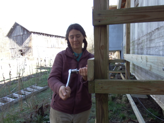
 In
the meantime, there's always the scary proposition that the unbalanced
tank might tip all the way over. I'm still not 100% sure we don't need
some additional support for the front edge, but so far I'm pretty happy
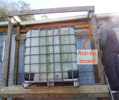
with Mark's solution of adding two boards across the top so the tank physically can't tip forward. (Only one board is in place so far. The other will go at the same elevation near the front of the tank.)
In
the meantime, there's always the scary proposition that the unbalanced
tank might tip all the way over. I'm still not 100% sure we don't need
some additional support for the front edge, but so far I'm pretty happy
with Mark's solution of adding two boards across the top so the tank physically can't tip forward. (Only one board is in place so far. The other will go at the same elevation near the front of the tank.)
So, engineers out there,
what do you think? If we put water in the tank, will our tower crumble,
or is it safely built? If you cringe as you look at our photos, what
would you add to the structure to beef it up and keep our water tank
elevated?
On a less geeky note,
adding a huge rain barrel to the back of the trailer suddenly changed it
from a blah space to an intriguing area full of possibilities. I can
hardly wait until I've added some plant life to give the region even
wider appeal.

Or explore more posts by date or by subject.
About us: Anna Hess and Mark Hamilton spent over a decade living self-sufficiently in the mountains of Virginia before moving north to start over from scratch in the foothills of Ohio. They've experimented with permaculture, no-till gardening, trailersteading, home-based microbusinesses and much more, writing about their adventures in both blogs and books.
Want to be notified when new comments are posted on this page? Click on the RSS button after you add a comment to subscribe to the comment feed, or simply check the box beside "email replies to me" while writing your comment.
As long as your tank is level, you should be ok. Once it's full it's not going to tip, unless it's very off-level. I built one similar this past summer, the only thing I see that might be an issue is how you've attached your supports to the uprights. It looks like the bolts are going to bear 100% of the load? What I did was notch the 4x4 uprights, so that the weight was born by the uprights instead of lag bolts. Here's a couple photos: https://www.flickr.com/photos/thebaldwingang/14703083212 and https://www.flickr.com/photos/thebaldwingang/14516706418/in/photostream/
Just a few things I see as potential problems. Your soil bearing capacity of the soil there is probably very low and you are concentrating a fair amount of weight into a small area. Assuming the bearing capacity is ok it may still settle unevenly allowing it to tip or shift the weight enough for the structure to collapse.
Another concern I have is that there is no diagonal bracing. You are depending on some very small diameter screws that will shear under load if the structure wants to fall most likely parallel to the trailer. Your carriage bolts are going to act as a pivot and only help in an absolute vertical bearing capacity and in short time those boards will be bowed. 2 bolts spaced apart on a single board would allow the bolts to help with some side to side sway but the diagonal bracing should be the main component of keeping this structure up-right. Typically I'd suggest putting the posts in the ground with compacted gravel fill or concrete if at all possible. This would help alleviate the structure from tipping this would require the posts to shear at ground level before they fell where your existing setup is already disconnected from the ground and has no lateral support. I wouldn't be as concerned about the tank falling off because the water weight will hold it down to the structure although if the structure was wider it would make it even more stable. A kicker from the structure out to a place further out in the yard (perpendicular to the trailer) may add to this. I hope Roland chimes in as well I feel this could be very hazardous as it currently is setup.
I agree with Adrienne's comments about the footer. In addition, I'd have a french drain below or around the footer, since you get so much rain. What you have might last for a while, but I wouldn't count on it staying level as is. And if it sinks in the front, you'll have a lot of weight pulling on your trailer structure, which might affect the roof. (I'm assuming the top braces are bolted into the wall behind).
Also, if the 2x6's aren't rated for that much weight, why not have 3 or 4 of them to make the "floor"? Plus I definitely would not have the edge of the tank hanging over the floor----just that is going to imbalance the structure & cause sinking in the front, thus pulling on your walls. The floor which holds the tank needs more depth.
I would think of this as a very small deck, for gut check purposes. In that case, if it's about 2300 pounds and about a 8x2 (16 square foot) structure then you're talking about roughly 140 pounds per square foot, or three and a half times the load on a residential deck (usually 40 psf). You can look up that load on an 8' span, which probably would need a 2x12 or a double 2x10 for beams (depending on wood species). Also, I would think you would need to add diagonal braces to prevent racking - parallel cross braces may not prevent the structure from tipping out of square. Your bolt calculations are probably good, but you need to be looking at the shear strength, not the tensile strength for this application (but on your table, shear is higher). Of course, if a structural engineer chimes in, please disregard the above! Let us know what you end up doing.
Hi All,
Lots of good ideas.
One that I would add is pretty simple. As currently designed a single failure of any of the 4 vertical posts or any of the 4 members that attach to them will create a very unstable situation. And the tank if partly frozen will be very heavy and hard to deal with.
It may not fail at once, but will be very difficult to fix.
So I usually add some backup safety to whatever design.
From what I see, 4 stacks of cement blocks under each corner of your tank would mean that a failure as above wouldn't be a big deal.
For better frost stability you could even put cement columns in that go below the winter frost line.
All simple cheap stuff :).
I find that keeping a bunch of cement blocks around makes simple stuff like this easy.
Right now I have a 100 gallon 'watering trough' (1/2 ton or so) on 2 blocks so I can heat it from below. Eventually it will become part of an aquaponics setup I am working on.
Lots of fun.
John
p.s.- I was looking at those tanks myself for garden use. Cheap and big :).
One last thing I just noticed. I think the IBC is intended to be support under the corner and mid-leg braces continuously. The way it shown in the photo shows the small tubing that allows it to stack on another IBC will bend.
Do you have more than 1 IBC? Maybe the safer route would be to create a solid level surface on the ground and stack them 2 high as they are designed to be. One tank would be higher for pressure and when it's full overflow to the lower tank which would not have much pressure. It may be cheaper to get a simple RV pump than to dedicate all your lumber to lifting this up for a little water pressure.
I will agree with Brian's comment of the current 2X6 boards are likely to bend/break the supports at the bottom of the tank. Ideally you would want the boards under the big metal blocks that the tank sits on.
I am interested in your ideas of how to support the IBC tank as I would like to do something similar this next year (low pressure drip irrigation for my garden).
Another source of water containers (that I got lucky and found) was left over wine making containers (commercial winery). I was able to purchase 100 and 500 gallon water containers.
In general, constructions cannot be simply read out of a table.
(there are e.g. design rules for how to build wooden houses, because they are somewhat standardized)
In this case there are a couple of things that I would like to check;
How long are the two joists that the IBC is sitting on? And what kind of wood are they made of? (the type of wood determines the load rating.) And how wide is the IBC? (you can also mail me these numbers if it's more convenient)
You did orient the joists so that they are most stiff, well done!
But as is, I'm not sure it's safe. I would advise you to not put water in it yet!
What I would urgently suggest is to add a diagonal beam from e.g. the left joint in the lower joist to the right joint in the upper joist for stability. You are basically building a truss. As you can see in the linked article trusses usually are built out of triangles. That is because if you connect the joists to the pillars with bolts (pins), the joints can rotate, and the structure isn't stable. Your rectangles could collapse into parallelograms! A triangle is inherently stable even if the joints are pinned.
Another point is how the pillars are sitting on concrete blocks. In general, those probably atract ground water rather than repel it. And since the end grain of wood is most liable to rot, I would advise you to seal the end grain and the bottom 5 inches or so of the pillars with waterproof paint or wood sealant. You wouldn't want a 2000 lb IBC landing on you because of wood rot!
Throw a couple diagonal braces at it as has been suggested and I think you will be fine.
My folks have a retired friend who was a mechanical engineer. The man is incapable of finishing a project...he over thinks everything. His place is full of unfinished projects.... My dad never had an engineering degree but he built a roof you can drive a tractor on!
Great comments, everybody! I think Brian nailed one problem point that I hadn't even considered --- the metal supports at the base of the IBC tank --- which is a good reason to add another round of supports under the front of the tank.
Several of you also mentioned diagonal braces, and I suspect you're right. Perhaps 2X4s will suffice?
Roland --- Unfortunately, I don't know what kind of wood it is, but would guess a southern pine (treated to be rot-resistant). The joists are 8 feet long and the IBC tank is about 39 inches wide in the smallest direction (perpendicular to the trailer), and I think 40-some inches the other way. (Not sure exactly and it's dark, so I can't check at the moment, but I think that's close.)
Anna,
I've found the strength data for southern pine, and a relevant standard for wood constructions (EN 1995-1-1, this is a European standard but I'd guess any US standard would be similar). I'll do a first order analysis on saturday.
I seem to recall that in the US, timbers are actually smaller than their listed sizes. Can you confirm that actual sizes of the members conform to the table listed in the link?
Could you hazard a guess as to what portion of the year the relative humidity is >85%? (higher moisture content lowers the strength of wood). It is relevant to choosing the right environmental class.
Off to my day job now.
Roland --- You're my hero!
To answer your questions --- yep, our "2X6"s are really 1.5 by 5.5 inches. I didn't know Americans were the only ones who skimped.
In answer to your humidity question --- I'd say a good portion of the year is higher humidity than 65%, but perhaps not so much is higher than than 85%. It's currently raining and 76% humidity outside.
Well to your comment on the sizes of the wood and why they are not their "reported size" it all comes down to the old days of sawing wood. The stated size was the size of the wood including the area cut by the saw the "curf" and also some cleaning of the board. So a 2"X4" piece of wood is now 1.5X3.5
In most cases the wood we purchase from the hardware store is going to be some form of Pine.
I'm from the building trades and if you guys were starting from scratch, I would give you different options but you can work with what you have, just have to modify it. First those 5/8 carriage bolts are plenty, so no worries. Problem is the size of those 2x6s. Much to small. I suggest doubling them up. Install a cross piece (2x6 or bigger) between the front column and back column on the inside of the structure for the 2x6s to rest on.
Then add another double 2x6 joist dead center.
Add a rim/band joist piece on both ends to center the joist and you can add two/three pieces of blocking evenly spaced in-between.
Lastly I would cut some 4x4s for the front and back for angle supports to help carry and cut down the load on those 2x6 joist.
I would connect all of these with Ledgerlok type screws. You can find these at Lowes which I believe is close to you guys. They are stronger than carriage/lag screws despite there smaller size. Cost is miniumal. You'll love them for other projects
Also cheaply you can use 1x4s for some diagonal cross bracing across the front and back in an x pattern. This will provide more stability than you think.
If you guys want to start over from scratch I can suggest a much smaller platform/less material.
According to my assessment, the current structure is unsafe and should not be loaded as-is.
I'm a mechanical engineer with two decades of experience, but keep in mind that I'm not a licensed structural engineer in the US! The following first order analysis is based on my reading of the relevant European construction standards because I'm not familiar with US standards.
Stability
All rectangular frames should at least have one diagonal bracing beam from one corner to the opposite corner, dividing the structure into two triangles. Two crossed diagonals would be much better, though. Without bracing a structure is liable to move much more under e.g. wind loads. Movement will loosen nail joints and cause them to fail.
The columns should be further apart in the direction perpendicular to the wall of the trailer so that the joists are under the front- and back metal rim under the IBC. As is, the structure is too unstable for my liking.
Unit conversions
Since I'm not used to working with imperial units, I'll convert all dimensions to metric using the units(1) software
Since forces have to be in Newtons, we'll convert the masses to gravity forces using F = m·g, where m is the mass in kg, and g is the accelleration of gravity at the earth's surface, 9.81 m/s²
General remarks
Stresses are expressed in N/mm² in metric units which is equal to megapascals (MPa). 1 N/mm² is approximately equal to 145 psi. For tensile and compresssion stress the symbol σ (lowercase Greek letter sigma) is used, while shear stresses use τ (lowercase Greek letter tau).
Properties of southern pine
Depending on density, when and where it is grown, southern pine is rated in the strength classes between and C18 and C24 (inclusive). You can find the characteristic strength and stiffnesses for those classes in this table.
According to EN 1995-1-1:2004, to get the design property, we should take the characteristic property from the strength class, divide it by the partial factor (1.3 for solid timber) and multiply it by a modification factor depending on load duration and environmental circumstances. See table 3.1 in EN 1995-1-1.
I'm assuming that this structure would have to withstand a full load between 6 months and 10 years. That gives us a load duraction class “Long-term” according to table 2.1 in EN 1995-1-1. Given that you often seem to have wet conditions, I estimate that a “service class 2” (according to §2.3.1.3 of EN 1995-1-1) is appropriate. For solid timber, service class 2 and long-term action a modification factor of 0.70 is appropriate. So we have to multiply the strength in the table by a safety factor of 0.7/1.3 = 0.5385.
Analyzing the joist
Bolt loads
According to Anna's figures, the front horizontal joist will be loaded with 6804 N (the design load). Assuming that the IBC is resting in the middle of the joists, that means each of the bolts that connects the joist to the pillars carries 3402 N. Assuming that the diameter of the bolt is really 5/8'' (15.88 mm) and the shear force is carried on the shaft and not on the thread, the average shear stress would be the shear force divided by the cross-section area 3402/(π/4·15.88²) = 17.18 N/mm², while the maximum shear stress would be twice that. Unfortunately I'm not familiar with US bolt classifications. But the lowest-grade bolt steel that I'm familiar with (European type 4.6) has a failure shear stress of 168 N/mm². Since the actual stress is much lower than the allowable stress the bolts will be fine.
Southern pine is rated in the European load class C18−C24. That means a compression strength perpendicular to the fibers of 2.2−2.5 N/mm². Multiplying that by the factor of 0.5385 the design strength is 1.2−1.3 N/mm². The projected size of the bolt hole through the joist is 16·38 = 608 mm². So the average compression stress that the bolt exerts on the hole in the joist is 3402/608 = 5.6 N/mm². The maximum compression stress would be 1.5 times that, so approximately 8.4 N/mm². This is significantly more than the design strength, so the bolts will crush the wood of the joist that it is going through!
To fix this, take a piece of 2x6, 4 inches long and nail it vertically to the 4x4 column under the joist with at least eight 8d nails (in two vertical rows, spaced 1 inch apart horizontally and vertically), so that the joist rests on this support piece rather than just rest on the bolt.
Shear stress in the joist
The cross-section of the joist has a surface area of 38 mm × 139 mm = 5282 mm². The average shear stress in the joist is 0.64 N/mm². For a rectangular cross-section the maximum shear stress is 1.5 times the average shear stress, so 0.96 N/mm². The characteristic shear strength is 3.4−4.0 N/mm², yielding a design strength of 1.8−2.2 N/mm². This should be OK.
Bending stress in the joist
On each side of the IBC, the distance to the bolt is approximately (2438.4 - 1016)/2 = 711 mm. The maximum bending moment (M) which occurs where the IBC rests on the joist is then 3402 × 711 = 2418822 Nmm. To calculate the maximum occurring bending stress we use the formula σ = (M·e)/I, where I is the second area moment and e is the distance from the neutral line to the top and bottom edge. For a rectangular cross-section with a width B and a height H, the second area moment is defined as B·H³/12, and e is H/2. Through substitution this gives σ = 6M/(B·H²). Given that B is 38 mm and H is 139.7 mm, the maximum bending stress is 6·2418822/(38·139.7²) = 19.57 MPa. For the C18−C24 classes, the characteristic bending strength is 18−24 MPa. Taking into account the safety factor the allowed bending stress is only 9.7−12.9 MPa. Since the occurring bending stress is much higher than the allowed bending stress, the joists will fail in bending.
To fix this, the vertical frames should be moved much closer to the IBC, making the joists shorter. Ideally, the vertical frames should be next to the IBC, but not more than approximately 300 mm (say 12 inches) away it. That will reduce the bending stress to acceptable levels.